|
|
|
|||||
|
|||||
|
|||||
|
|||||
|
|||||
|
|||||
|
|
||||||||||||
User documentationWe tried to minimize the modifications required in your project to integrate
CorbaTrace. We only use OMG methods to install it. RequirementsTo run CorbaTrace, you must have :
To be able to see the generated sequence diagrams in XMI or Tex, you must have:
CompatibilityIt should work properly on other systems, as we use only standards like Java and XML, but only made a few tests. If you have some compatibility troubles, please mail us. See below for the tested configurations:
One of our futur work is to be compliant with the GNU project. So we will try to be compliant with GCC 3.0 and classpath, and with a free ORB. All should be possible and not so hard because we only use standards. Integrate CorbaTrace in your projectYou have an example of a Server and one of a Client in ./src/java/corbatrace/hello. Just include the CorbaTrace.jar in your CLASSPATH. In the sources, add at the beginning : ClientIn your sources, before the creation of the orb, initialize the interceptor
by creating an instance of the You can get your own object by using the standard function : Once all objects are created, add : "My Name" is used to identify your component. All client objects on the same ORB are seen as a same component. If you want to change the logging policy, call : See below for an example :
You can download all the code of this example of Client on our CVS: Click here. ServerIn your sources, before the creation of the orb, initialize the interceptor
by creating an instance of the After the initialization of the orb, call a method to resolve the references
of the RootPOA : Get your own rootPOA by using the standard : Then create the POA which calls the method "create_poa" of the class InterceptorServer
: Activate the object on this POA : This method records and activates the object of the POA that has just been
created. This POA will enable client applications to have access on it. Get your own object by using the standard : Write your object "hello" to a file (or register your object on the CosNaming
service) : The server waits for the requests of the clients and answers by calling
the appropriate methods : Before closing, destroy the server : See below for an example :
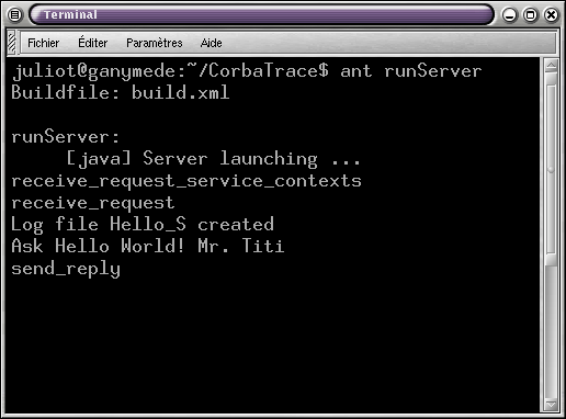
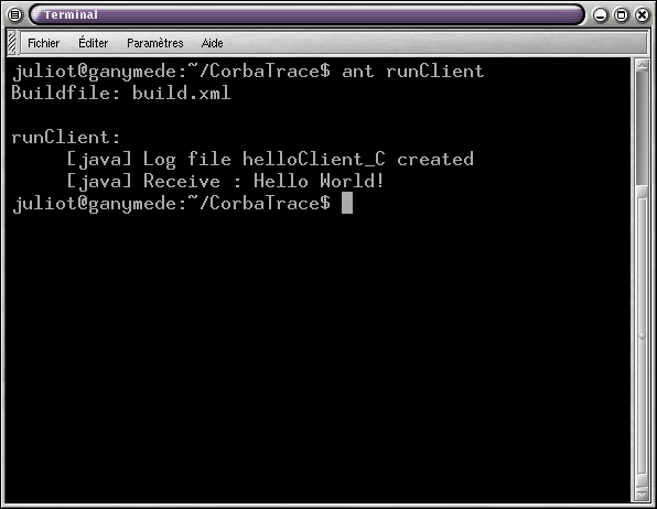
You can download all the code of this example of Server on our CVS: ResultCompile your project and run it. You can convert them to XMI and use some filters (see below). ScreenshotsWhen you execute our example, you obtain the two screenshots beelow :
After interception, two logs are generated (files linked) :
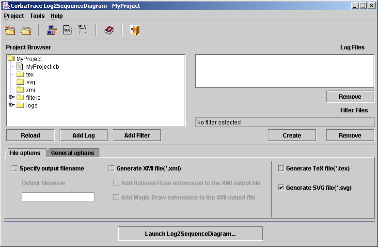
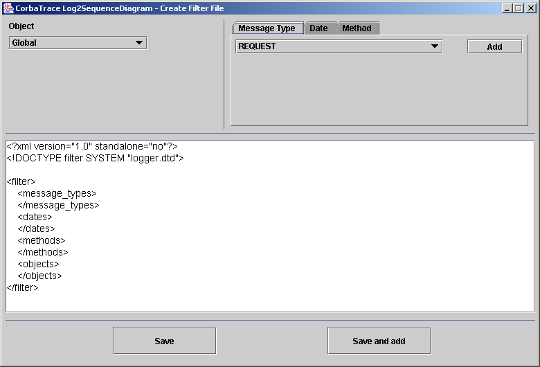
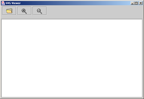
Generate an UML sequence diagramAfter the logs of your interceptions have been created, you can process them with our tool (Log2sequencediagram) to generate a UML sequence diagram in SVG, XMI or latex format.This tool has four purposes : - parse your log files, and merge all partial-messages to get full messages - synchronize all local objects clocks to a common clock (as it's often distributed on different computers all over the world). - apply some filters of your own to get more relevant informations - generate a file that you can directly display with the tool GUI for a SVG file, on common UML tools such as MagicDraw and Rational Rose for an XMI file. To launch the GUI of Log2sequencediagram, the command is : ant gui In this GUI, you can select the logs files you want to use to generate the UML sequence diagram, the filter file, the options of the generation,... This GUI also provides some usefull tools like a light FTP client to get distant logs files, a easy filter creation GUI (see the part below to know what is a filter) and a SVG viewer to display the SVG sequence diagram. Here is a presentation of this GUI :
Click on the GUI area on which you want informations.
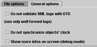
Project browser: Log files: Filter: Output file: XMI Generation: TEX Generation: SVG Generation: Validation: Synchronization: Show more infos:
Click on the GUI area on which you want informations. Local folder: Distant folder: Get button: Get button:
Click on the GUI area on which you want informations. Object:
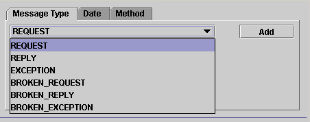
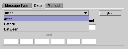
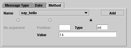
The combo box is populated with the objects which are in the log files added in the Main window. The filter parameters:
By clicking on the Add button, you add this parameter on
the selected Object (see
Object). The filter display: The 'Save' button: The 'Save and add' button:
Click on the GUI area on which you want informations. The tool bar: The display: FiltersFilters are written in an xml file, as defined in the DTD (log.dtd)It works at two levels :
For given objects, you can also restrict your messages more precisely to given message types, dates, and operations, with same principles as at globally level. Each different filter (date - type - object - methods) works as an "AND" with others. Each component of a filter (all dates for a date filter, all arguments for an method filter, etc.) works as an "OR" with others. For example : (filters.xml)
This messages filters keeps messages that : are of type broken (any of them) Of course, this is an example. Here, giving the messages types as broken for object "anObject1" is useless as it is already defined globally for the same type of messages. Display the UML sequence diagramsThe file generated by the Log2sequencediagram tool can be of three types:- SVG - XMI - Latex * SVG : The CorbaTrace team recommend to use the SVG format. The main reason is that with this format you don't have to use a external UML tool like with the XMI format. And you have a much better graphical quality with the SVG format than with the Latex one. To see a SVG file, you can use the SVG Viewer provided with the Log2sequencediagram GUI presented above. You can also a web browser with a specific plug-in. * XMI : The DTD of the XMI file generated is the uml13.dtd of the XMI standard, corresponding to version 1.3 of the UML metamodel. XMI is a standard format for storing and exchanging UML data. It is a quite new standard. Many UML design tools already use this format, some as export format, some as saving format. Even if XMI was created to be an exchange format between UML design tools, every tool developped some proprietary extensions format. These extensions are added in most cases at the end of the XMI file, and hold all the graphic data for drawing the diagrams. We decided to program the XMI extensions for 2 XML design tools: MagicDraw UML and Rational Rose. Nevertheless, maybe some other tools are (or will be) able to display diagrams without any other data as the standard XMI. MagicDraw UML: MagicDraw UML is the best tool for displaying XMI files, because its architecture is based on XMI. It is not free, but you can download an evaluation version. This evaluation is only limited in the number of actors and classes when you save a file. That's not a problem here, because the file already exists and we only want to display it. To load our XMI file, only choose "File->Open project..." and select the xmi file. You must have the uml13.dtd file in the same directory, while MagicDraw validates the XMI file. You can get this dtd file in ou download section. When you open our XMI file with MagicDraw, you get an error message saying "wrong metamodel version". Don't matter. This is due to the fact that for having the compatibility with rational rose we had to set the metamodel version to 1.0 instead of 1.3, even if the effective DTD we use is the DTD of metamodel 1.3. You can change this in the XMI file if you want (see where my comment is). Example : The XMI file with MagicDraw extensions: click here to get it. Screenshot: the tree 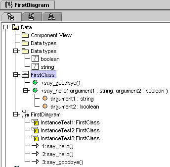
Screenshot: the diagram 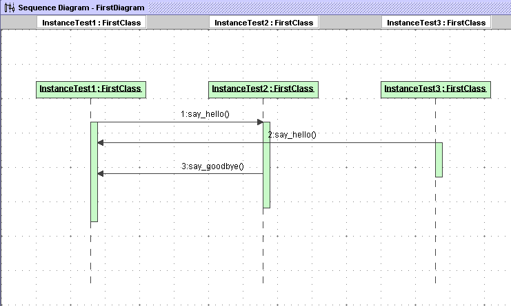
Rational Rose : To be able to import XMI files into rational rose, you first have to download a plugin. You can get it at this addess: http://www.rational.com/support/downloadcenter/addins/rose/ . This plugin only exists for the windows platform. Once installed, you can import XMI files by choosing "File->Import UML XMI file". You must place your files in the "XML files" directory of the directory where you installed the plugin or copy the "dtd13.uml" file in the same directory as your XMI file. If the creating wizard window opens, click "cancel", to continue import. During the import, some errors occur: warning messages are displayed, click "No" each time (normally 2 times). That's because we use the 1.3 version of the UML metamodel and the Rose XMI plugin supports only version 1.0, so some tags are not understood. After that, Rose says "the mdl file does not exist" (of course, it is creating it from the XMI file!). Don't matter again. Then you get the message "import complete", and you can see your Sequence Diagram. You have an empty "data types" package, because the plugin can't import the data types. Don't care. If you can, download MagicDraw UML and use this tool, it's much better with XMI!!! Example: The XMI file with Rational Rose extensions: click here to get it. Screenshot: the tree 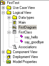
Screenshot: the diagram 
Other UML Tool : We need your help. Poseidon (and ArgoUML) are some free UML tools and they use XMI too. It would be not very difficult to create a new extension for CorbaTrace to generated good diagrams. However, XMI can be enough to show lots of informations, without any extensions. * LATEX : You can also use latex to display diagramm sequence. You must use the msc.sty package for sequence diagram. You can hace it in our tar/gz or on our website. To run it, you must generated the XMI file with Log2XMI. And after, you just use : example : If you want more informations or help, you can see our report and presentation. Go to our develop docs section. Enjoy. |